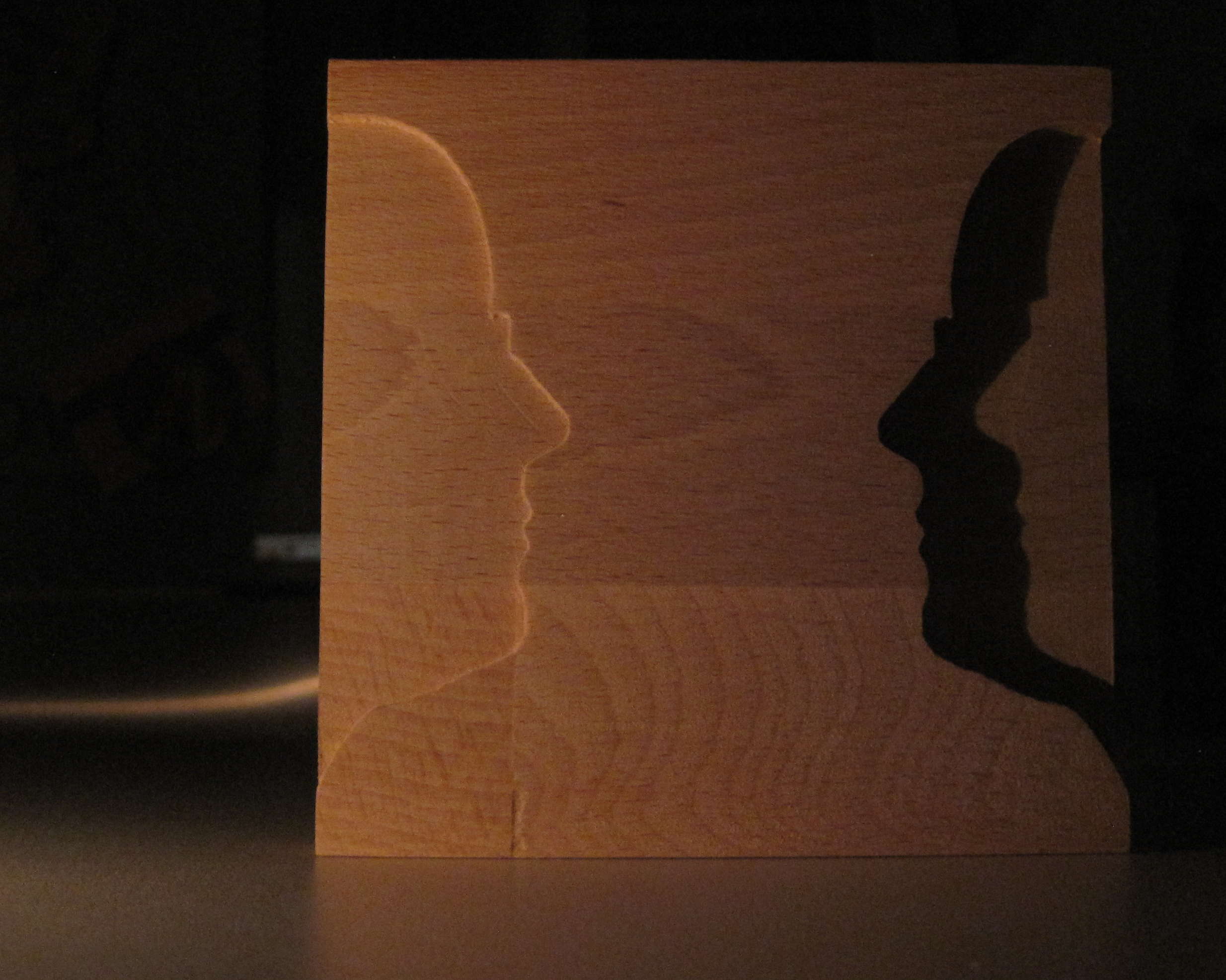
Silhouette
This thing does not serve any particular purpose. It is just playing with the silhouette of my wive cut out of wood and a candle for illumination.
Silhouette
This thing does not serve any particular purpose. It is just playing with the silhouette of my wive cut out of wood and a candle for illumination.
I somehow lost the knob for selecting the power of my microwave. It took several iterations but I finally made a new one. It is not winning any prices for beauty, but it works.
It is made out of two parts: The thing that acually plugs into the microwave and a round knob. That way I can replace them idependently when one breaks.

Microwave knob (back side)

Microwave knob (front side)
Again I spent some time searching for free tools to improve my cnc toolchain. I stumbled upon two simple but helpful flash programs for handling g-code files:
I spent several hours searching the internet for a CAM program, that can generate g-code from my CAD drawings. There is a lot of partially functional programs or some for very specific purposes, but nothing really pleasing. Finally I found HeeksCNC (http://code.google.com/p/heekscnc/downloads/list). It has some issues as well, but I like the general concept.The g-code is generated semi-automatic where the user has to define the shapes the machine should process.
If you import models from FreeCAD for example, then the workflow is:
I built a CNC machine recently and one of the first things to do is of course to improve it. I used fritzing (http://fritzing.org/) to draw my circuit. When I was done I realized that I had no software at hand, that could make g-code from the exported gerber files. After some research I found:
I managed to produce a one layered pcb that now drives my CNC machine.
I am doing audio recordings as one of my hobbies. Part of my equipment is the Tascam US-1641 external USB soundcard. When I set the device up for the first time, I was angry that the software, that came with it (some Cubase light edition) forced me to do a long and painful registration. Of course there is no linux driver (which I could have checked before I bougth the device) and besides audacity (which isn’t a digital audio workstation) and other expensive software I couldn’t find software for Windows I liked. So I finally registrated the software to be able to use my new soundcard.
I have been using linux only for a long time. Now I had to boot into a Windows installation only for doing recordings. The audio editing I always do with Audacity and Ardour anyways. So this was all in all a very invonvenient solution. I contacted the customer support and asked for linux drivers. Tascam only pointed me to some other devices with linux support. These weren’t official driver by Tascam, but instead some linux enthusiast wrote ALSA drivers for the devices he owned.
I looked into these drivers to find hints what to do with my US-1641. Sadly I couldn’t figure out how they work and I also failed to understand the concepts behind ALSA driver development. I finally gave up and decided to take a different approach.
I need the device for recording audio. I don’t want to listen to audio with it and I have no need for realtime and low latency. So I decided to directly grab the data from the device without using ALSA or JACK. This way I could concentrate on the USB communication and I could skip the time-critical complexity of the linux audio systems.
I read some theory about USB communication (http://www.beyondlogic.org/usbnutshell/usb1.shtml, http://en.wikipedia.org/wiki/Universal_Serial_Bus) and quickly stumbled upon the libusb project and its documentation (http://libusb.sourceforge.net/api-1.0/). The libusb is great and it is my choice for doing the low level USB communication. Of course I didn’t want to (and am not skilled enough to) reimplement the whole USB stack. The libusb makes sending and receiving data from a USB device very convenient. Now I “only” needed to figure out what to send and what to read. That is of course the trickiest part, because there is no specification publicly available which describes the communication protocol between the Tascam US-1641 device and the Windows driver.
The USB protocol itself enforces, that a device provides basic descriptors about its capabilities. This data can be displayed using the linux tool “lsusb”.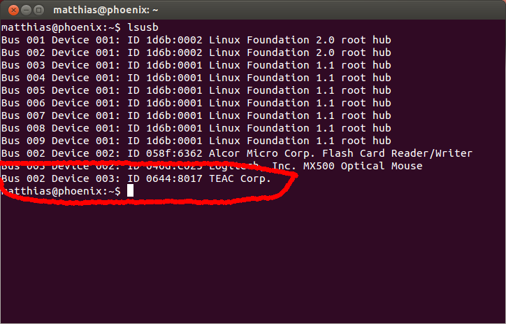
Even without any driver a USB device registers to the system. It shows the vendor ID (0x0644) and the device ID (0x8017). These are used to identify the device later. Currently it is connected to Bus 2 and has the number 3, but these might change when the system reboots or if you plug it into another USB socket. But lsusb can do more. Run “lsusb —v”. You get a long list with details about every USB device connected to the system. Have a look at this textfile to see the whole output lsusb.txt
What I learned from this data
So what next? I learned a lot, but still didn’t know how to use the soundcard. I suspected that it had to be initialized by some magic, but how to find out? First I used USBSnoop running on my Windows where I also had the original soundcard drivers. I wasn’t happy with the software so I installed VirtualBox on my linux machine. I installed Windows in a virtual machine, setup direct access on the USB port and installed the soundcard drivers. What is the difference to the previous approach? I could use Wireshark which not only understands networking protocols, but also USB. I started logging with wireshark, powered on my soundcard and watched the data flow to my virtual Windows machine. I noticed that the USB connection between Windows and the soundcard wasn’t very stable. I wasn’t able to really play sounds on the virtual machine, but nevertheless I got a lot of useful information.
First I had to filter out all USB messages that were not for my soundcard. I was surprised to see how much traffic there is even when I do not use any devices. The lsusb command shown above gave me the current device number (here it is 6) so I could filter for all messages for this device.
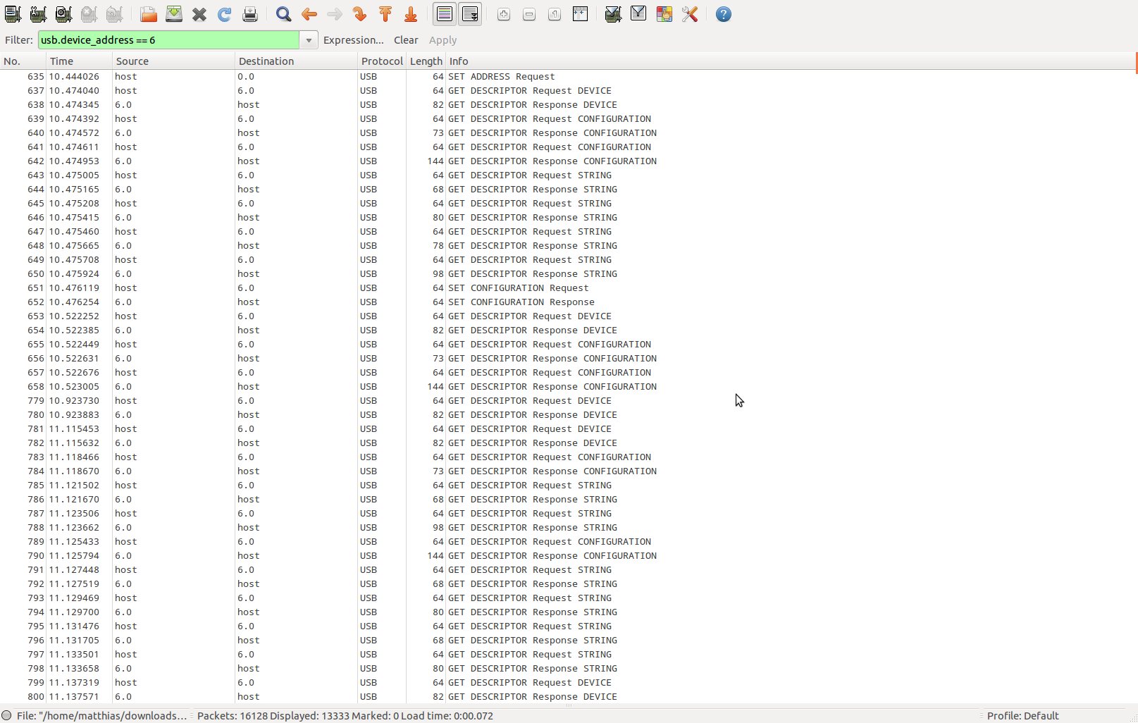
I inspected these messages and found that these messages contain the information that is also output by lsusb. So nothing exciting going on here. But then there was something special:
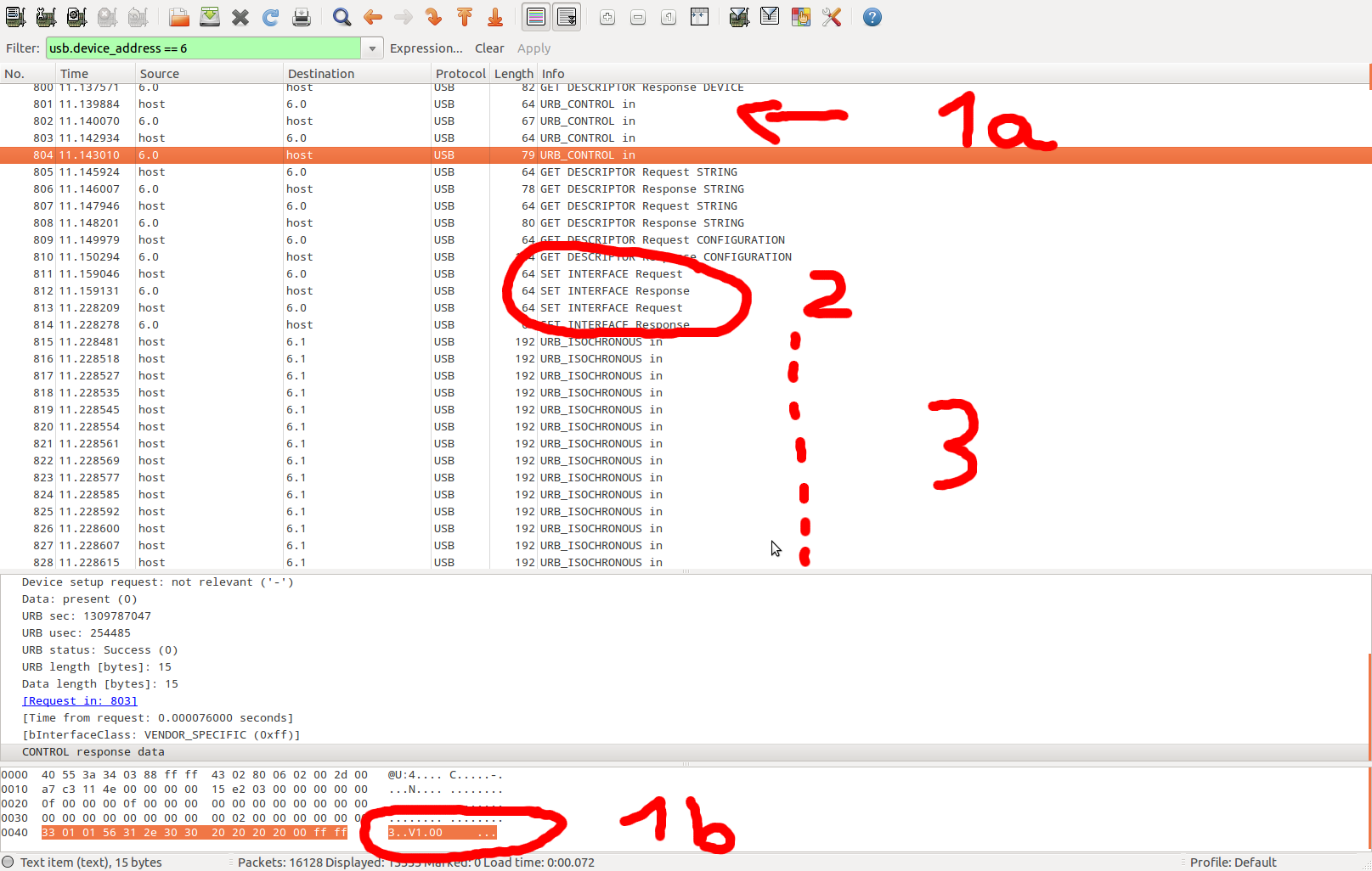
The parts marked as “1a” and “1b” show a control transfer going on. This transfer contains a version number “V1.00”. The same number was shown in the the Windows driver. This is nothing really useful, but it showed me that there was something going on that I could understand.
Section “2” activates the alternate settings of the interfaces. These inferface settings I already spotted in the lsusb data. Directly after activating these settings, wild isochronous transfers begin (“3”).
I switched the soundcard off and on several times and quickly assembled a list of control transfers that take place only when the device is initialized. After that data was transmitted to the soundcard using isochronous transfers. I also found a lot of big bulk transfers from the soundcard to the pc. I also noticed, that the data packets all looked very similar.
Based on my observations I decided to write a small programm that just replays all control transfers I found. Most of the transfers contained values I did not understand. Others were obvious (like the version number). The program continuously reads bulk data packets from the soundcard and sends packets containing only zeros. You can get the simplified source code here:
Don’t expect too much from this program. It doesn’t do anything useful yet. It plays silence and discards all data it reads from the soundcard. It shows you what I did to communicate with the device and you might use it as an example of how to use the libusb. I will extend this program to actually do something in another post.
My approach was successful. The dataflow started and inspecting it with Wireshark showed similar behaviour to the original driver. I successfully transmitted data to the soundcard and read data from the soundcard. I didn’t need to take care of any timing. Sending and receiving data as fast as possible works because the soundcard refuses to recieve data as long as the previous packet wasn’t processed. Receiving data from the soundcard only works when a complete data packet is available. Once it has been transmitted the soundcard refuses to send data until a complete new packet is assembled.
The biggest problem still was unsolved: I didn’t have any idea what data the packets contained. This is discussed in a different blog post.

My gradfather owned a Hohner Pianet N. Sadly it stopped working several years ago and spent the last years merely as decoration for his flat. After he died I had the choice between scrapping or saving it. I didn’t like the thought of a musical instrument beeing scrapped, so I kept it and hoped to repair it one day. This is what I did and here are some things about the process that I want to share.
First of all: I like the manuals and advertising, that came with the Pianet. It is so different from everything you see today.
ServicingInstructionsAmplifier
Let’s start with details about the Hohner Pianet N itself.

It is mostly made out of wood, therefore it is quite heavy and it makes it look like a piece of furniture and not like a technical device.

The box, that contains the electronics, is shielded with some metal foil glued to the inside of the box. (bottom part, back wall, top cover)

The circuit board has only one side with copper traces (back side), the front side holds all components. There are only discrete elements built into the circuit. Transistors, resistors, capacitors, a photo-diode, a small light bulb (removed), two variable resistors and wires. this makes it easy to match the board to the circuit diagram that came with the device. The black pieces sitting on the metal rods are called sticky hammers.

Sticky hammers: The right one is the original, the left one is the replacement made from silicone.
What astonished most about this device is the fact, that the whole thing is designed for easy access to all its parts and easy replacement of parts. All you need is a screw driver, a soldering iron and the part you want to replace. Of couse this is the toughest part, because there are no original replacement parts anymore. However it feels great to know that you could repair it easily. This definitely isn’t true for any other device I dismantled so far. It is even better, that the device manual contains detailed schematics.
Let’s continue with a short description of the inner workings of the Pianet.
The way the Pianet generates sound is fundamentally different from other keyboard instruments. Harpsicords and pianos have strings as the basic sound generator. On pressing a key on a harpsichord a string is plucked, while the piano hits the string with a special kind of hammer.
So what happens when you press a key on the Pianet? Check this image first:
Some keys with attached rods, which carry sticky hammers sitting on metal reeds.
The key is connected to a metal rod. This rod has a sticky hammer attached to its end. This hammer is glued to the metal reed for this key with some very weak adhesive. When the key is pressed the hammer rises and pulls the metal reed with it. At some point the force of the lifting key exceeds the force of the adhesive sticking to the metal reed. The adhesive rips of and the reed starts vibrating, which creates the sound. It fades out until you can’t hear it anymore or until you release the key. After releasing the key the glue sticks to the reed again, stops its vibration and the key is ready to be pressed again. This process sounds a bit like playing the chimes.
But wait – isn’t the Pianet an electric device? Yes it is and the story continues. The metal reeds are attached to a metal bracket with one end while the other end can vibrate freely. Next to this vibrating end there is a straight metal bracket leaving a gab of approximately 0.5 mm to the reed. One of these brackets is connected to ground, the other one to 300V. Together the form a giant capacitor separated by air as the dielectric. Pressing a key lets a metal reed vibrate, which causes the capacitance to oscillate slightly. This causes a small charching/discharching of the capacitor, therefore causing a small alternating current alternating with the same frequency as the metal reed. This alternating current is first amplified in the Pianet, then fed to the Footswell, back into the Pianet and then finally to the audio output connectors on the back side of the pianet.
The Pianet also has a vibrato effect built inside. When I studied the schematics and the circuit board I was really amused how this effect was achieved: There is an oscillator circuit built into the circuit, that flashes a small light bulb a few times per second. Next to the light bulb is a photo resitor which catches the light. This resistor is part of the amplifier stage of the Pianet, so the flashing of the light bulb toggles the amplification factor between “high gain” to “low gain”. A simple, yet surprising way to solve this task.
Condition of the Pianet, when I got it.
The device is pretty old and so are all its parts. I first had a look inside the device, the amplifier and the schematics in the manual. Things I noted were:
Then I began my work.
I googled for the sticky hammers and found a webpage dedicated to some Hohner devices: http://clavinet.com.
They sell sticky hammers made of silicone, which work better and more durable than the original ones. Additionally they offer upgrade kits containing all capacitors and two resitors neccessary for my Pianet circuit board. I was lazy that day and ordered the upgrade kit instead of getting the parts myself. Some weeks later I recieved the parts. (The delay was not caused by clavinet.com. They sent out the stuff one day after they recieved my order).

I ordered these parts from clavinet.com. On the top is some copper shielding tape for reducing noise created by the keys. In the middle is the bag containing replacements for all capacitors and two resistors. The bottom shows the new sticky hammers made from silicone.
Reworking the circuit was pretty straight forward. Clavinet.com also offered some annotated photos which made the replacement very convenient. Here is a copy of the tutorial from clavinet.com (Upgrade Pianet N). When I was done soldering I connected the Pianet to mains and waited for it to explode, which luckily didn’t happen.
Now it was likely that I had a working circuit board. I tested it with the Pianet amplifier, but as I expected, it was not working due to the leaking capacitors. I needed another way to test it. Finally I decided to connect it to my stereo. The output of the Pianet is rated with 300mV max, Google told me how to connect the audio signal and ground to a standard audio jack, the schematics contained information where I had to hook into the circuit and I was ready to go. But nothing happend. I turned to the schematics again and finally I understood why it wasn’t working. I had no Footswell. Its purpose is to dampen the audio signal to add some way of volume control. By-passing it was easy and I finally got something (Recording of first sounds I got test1).

The green wire connects to ground, the yellow wire connects to the mono audio signal of the Pianet. The white wires are actually both ends of the same wire and they by-pass the loudness control by the Footswell.

The green wire connects to ground, the yellow wire connects to the mono signal from the pianet.
The green wire connects to ground, the yellow wire connects to the mono audio signal of the Pianet. The white wires are actually both ends of the same wire and they by-pass the loudness control by the Footswell.
The sound was dim, there was a lot of humming, but it worked. So things left to do:

The blue wire by-passes the connector for the footswell, which controls the loudness. Without the blue wire and without a pedal (which I don’t have) the device is muted.

The connector is easily hackable by opening the locking mechanism on the top side of the white plastic.

This is the connector after dismantling it.

Here is the connector with the additional chinch output added.
This is a recording of the final result: test2
Future work: Learn how to play.
The problem is, that libusb requires write access to USB device nodes. Check the entry
SUBSYSTEM==”usb”, ENV{DEVTYPE}==”usb_device”, MODE=”0664″
in the configuration file /etc/udev/rules.d/libusb.rules. If the file does not exist, create it. Adjust the entry to fit your needs. Maybe it is an alternative to add the current user to the group that has full usb access.