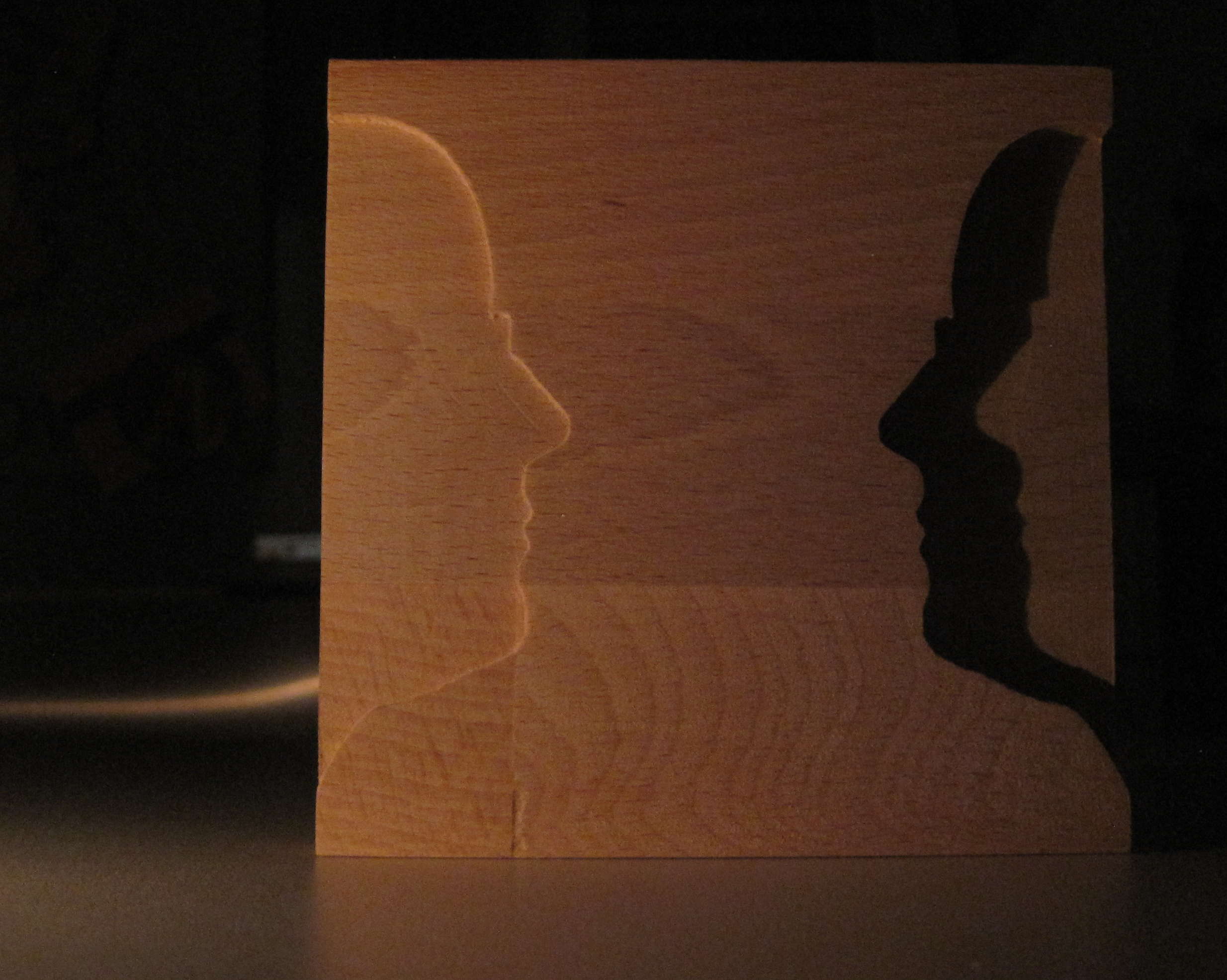
Silhouette
This thing does not serve any particular purpose. It is just playing with the silhouette of my wive cut out of wood and a candle for illumination.
Silhouette
This thing does not serve any particular purpose. It is just playing with the silhouette of my wive cut out of wood and a candle for illumination.
I somehow lost the knob for selecting the power of my microwave. It took several iterations but I finally made a new one. It is not winning any prices for beauty, but it works.
It is made out of two parts: The thing that acually plugs into the microwave and a round knob. That way I can replace them idependently when one breaks.

Microwave knob (back side)

Microwave knob (front side)
Again I spent some time searching for free tools to improve my cnc toolchain. I stumbled upon two simple but helpful flash programs for handling g-code files:
I spent several hours searching the internet for a CAM program, that can generate g-code from my CAD drawings. There is a lot of partially functional programs or some for very specific purposes, but nothing really pleasing. Finally I found HeeksCNC (http://code.google.com/p/heekscnc/downloads/list). It has some issues as well, but I like the general concept.The g-code is generated semi-automatic where the user has to define the shapes the machine should process.
If you import models from FreeCAD for example, then the workflow is:
I built a CNC machine recently and one of the first things to do is of course to improve it. I used fritzing (http://fritzing.org/) to draw my circuit. When I was done I realized that I had no software at hand, that could make g-code from the exported gerber files. After some research I found:
I managed to produce a one layered pcb that now drives my CNC machine.